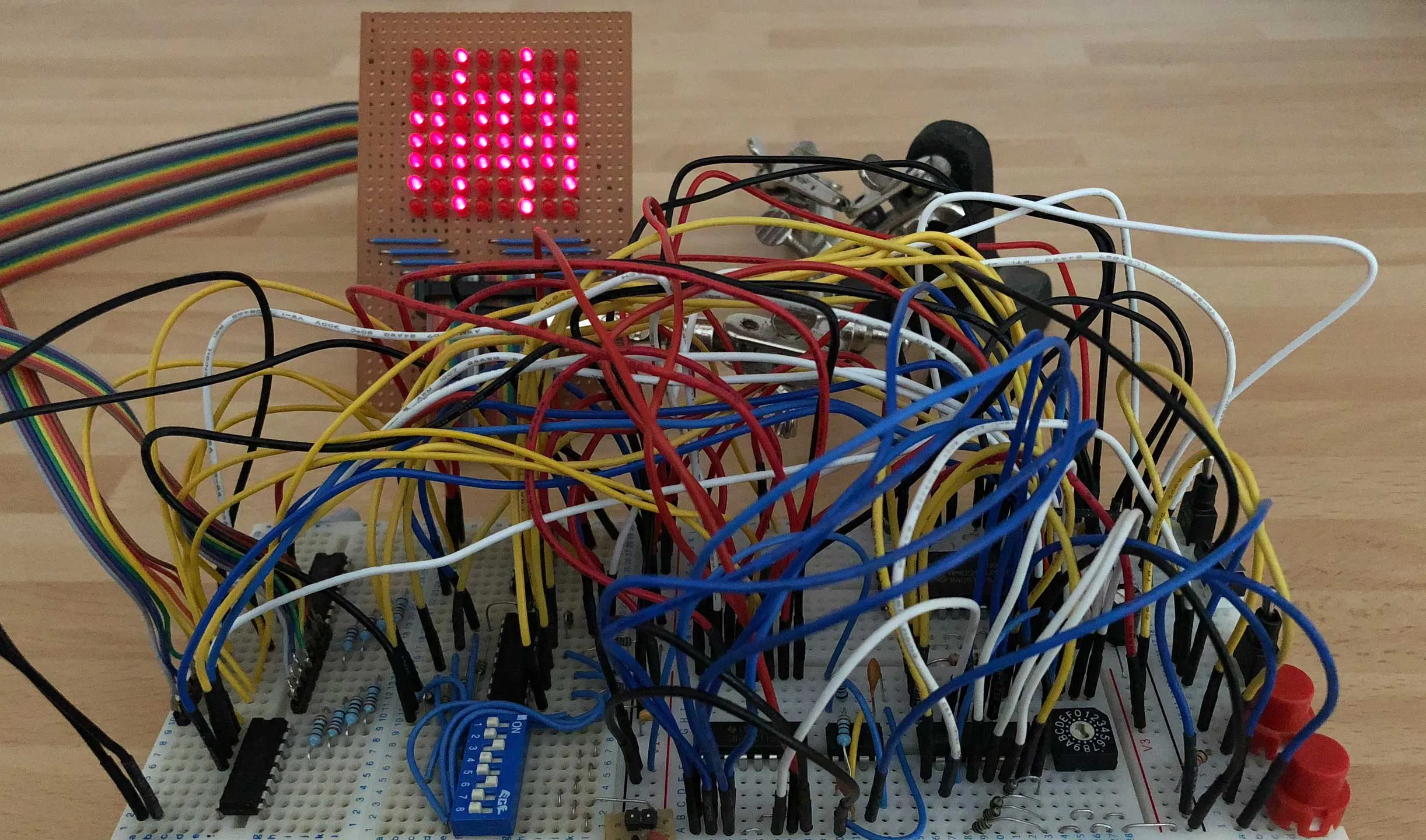
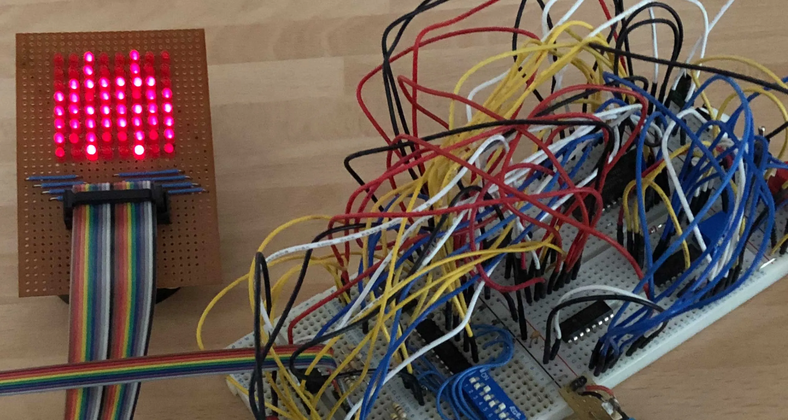
"Programmable" LED Matrix Driver without a Microcontroller
A quick weekend project to see what I could make work with the parts I had laying around. This one’s been in the back of my mind for a while so it was time to give it a shot. Using some basic logic chips, 555 timer, and an old static RAM chip, I put together this circuit which can display any pattern you can fit on an 8x8 LED matrix.
The way it works is fairly simple:
- A pulse from a 555 timer increments a counter through the numbers 0 to 7 (more on this under the “Ghosting” subheading below), 900 Hz appeared to give the brightest result without any flickering.
- The 3 bits needed to represent the number 0 to 7 in binary are fed into a 3-to-8 line decoder/demultiplexer, which then goes through an inverter and then Darlington driver chip, so that the output of the decoder enables only 1 row of the LED matrix at a time.
- The same 3 bits going to the decoder are also fed to the address pins of the RAM. The data output from the RAM then turns on the appropriate LEDs for the currently active row.
- The counter advances and then the next row of the matrix is lit up. Repeat this fast enough and you get an image showing on the matrix.
Ghosting
I was pleasantly surprised to find the circuit worked, but unsurprised there was at least one problem: the LEDs on one row were “ghosting”, i.e. bleeding onto the row below.
The problem was down to timing: when the counter advances to the next row, it takes time for the RAM to catch up and also the LEDs to fully turn off via their drivers before it’s time to display the next line.
Thanks to u/other_thoughts on my original Reddit post for the tip on an easy fix. It uses a 4 bit counter, but I only need 3 bits to address the 8 rows of the matrix. I could have been resetting my counter at 8, but instead was just letting it go all the way up to 16 before rolling over, essentially creating a vertical blanking period.
The solution is to use the least significant of the 4 bits as an enable pin. Since this alternates between 0 and 1 on each clock cycle, just feed this into the chip enable inputs on the decoder. This means that the individual rows are only addressed on the odd numbers from 1 to 15, and no LEDs are on during the even numbers 0 to 14. This creates a gap which gives them enough time to fully turn off before displaying the next row. You don’t even need to set the data of the even rows to all zeros in RAM.
So a small change to the wiring and no additional parts fixes the ghosting problem.
Programming
Since there’s no microcontroller, there has to be some sort of interface to set the appropriate bits in RAM for the image that you want to display. A rotary hex encoding switch is used to set the address, and DIP switches for setting the inputs. A few other buttons for control flow and a lot of tedious switch toggling later, you have your image on the matrix.
The programming sequence is as follows:
- Use the rotary switch to set the address to the first row, so binary 0001, and load this into the counter by holding down “Load Row Address” button and pressing “Advance Counter” once.
- Toggle the DIP switches to turn on and off the LEDs for this row.
- Press the “Store” button to write this data into RAM.
- Advance the rotary switch 2 places to the next odd number. Row number 2 is at address 3, or 0011 in binary, then latch that address into the counter again.
- Again set the DIP switches for this row and “Store” them into RAM.
- Repeat for all the rows in the display.
- To view the whole image, first change the mode switch from “Store Mode” to “Read Mode”, so that the LEDs display what is stored in RAM rather than the bits from the DIP switches.
- Then switch on the “Run” switch to enable the 555 timer to drive the counter.
What next?
After fixing the ghosting problem, the circuit works reasonably well, although there are a few improvements that could be made:
- When running, the image displays fairly dim compared to a single row in programming mode. I suspect this is a limitation of driving the LEDs between the RAM and driver chip. A buffer on the output of the RAM should fix this.
- A cleverer clock/counter section should prevent the need for skipping even numbered addresses to fix the ghosting problem but still ensure there is a blanking period between each row.
- This obviously only displays a single static frame, but what if I wanted to animate multiple frames? There’s plenty space in the RAM—I’m using an embarrassingly small fraction of its full capacity—and by adding additional counters to address frames it could cycle through these at any rate I set. But that’s sounding more like an experiment that would be fun on an FPGA and I feel like I’ve taken the wiring here to the limit of what I want to build for now.
I wasn’t initially able to find anything similar, but after I had most of the circuit working and in researching my ghosting problems I came across this similar project in the form of coursework from Cambridge University, so it’s interesting to see a slightly different approach to the same task.
Brightness update
So as pointed out by a helpful commenter on my second Reddit post, it was noted that the reason for why the LED matrix was so dim was due to the blanking row I was inserting between each active row from the ghosting fix.
Basically, LEDs are only lit for half of the possible amount of time as the blanking interval was a full clock cycle every other time. A better approach would be to change the duty cycle of the 555 timer output to something nearer 100% than 50%, and feed that into the enable input of the 3-to-8 line decoder. I found a combination of values which worked at a duty cycle of 82%, so now the blanking interval was only 19% of each full clock cycle.
I had to add a reset now once the counter reached 8, otherwise the display would still be as dim due to having a horizontal blanking period while waiting for the counter to go all the way to 15. Since the reset line is active low I had to just pass the 4th bit of the counter through a spare inverter and back to the reset input. Now I no longer need to skip every second address in RAM and the display is a lot brighter.