Modding a sheet metal brake into a box and pan brake
I’ve been using the Clarke brand vice-mounted sheet metal brake for a few years now and it’s been useful for various projects and handled both sheet aluminium and steel without issue. But more frequently I found myself wishing I had a real box and pan (sometimes called finger) brake for when I needed 2 folds on the same corner.
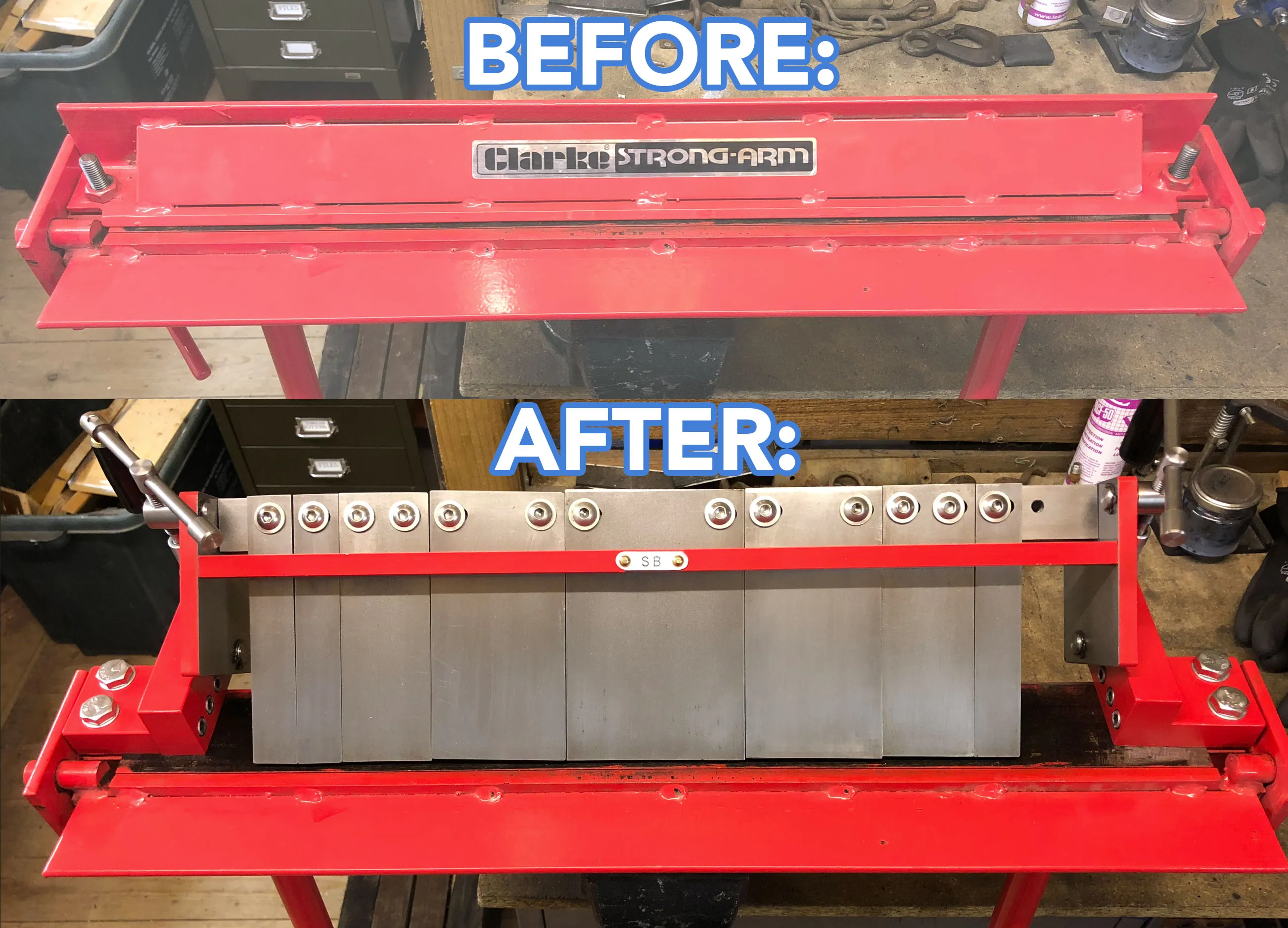
Looking at commercial box and pan brakes were both bulky and expensive for a tool that I don’t use all that often. My current brake already had the base and hinged folding bar; I just needed a way to add some fingers.
I developed this design that allowed me to retain a large part of the original Clarke brake, allows the brake to still function as original, and also could be built without welding (but would probably still be easier to build if you can weld).
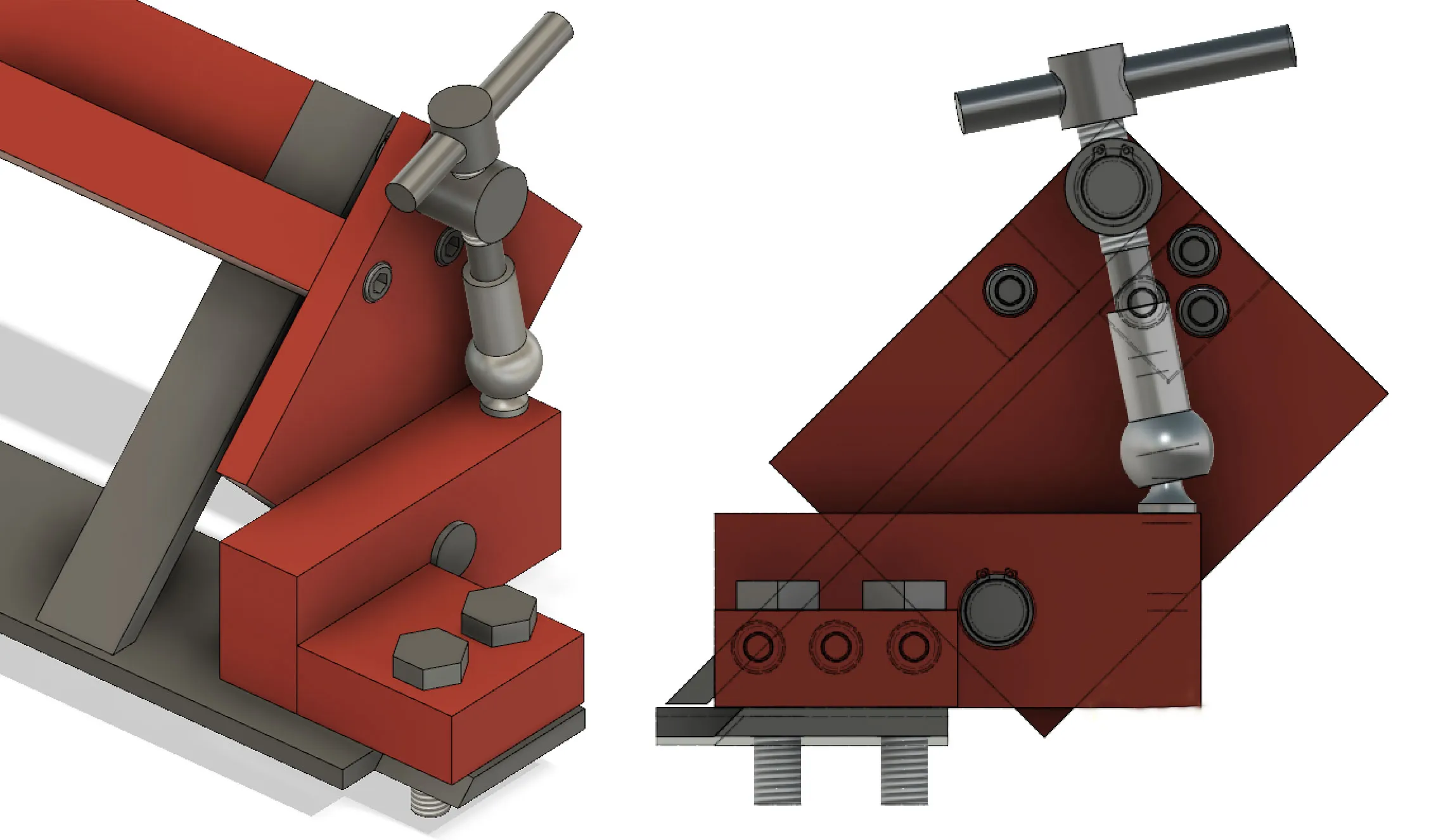
More sophisticated box and pan brakes use a lever and cam mechanism to lock down the fingers but I could not find a simple enough way of building it what way. Instead the key part is a ball and socket joint paired with a screw on each side to provide the clamping force. The ball and socket joint actually turns with the screw and is only ever being pushed down on, i.e. there is never any force trying to pull the joint apart. A cam mechanism would be faster if you’re using this tool all day, but I’m not.
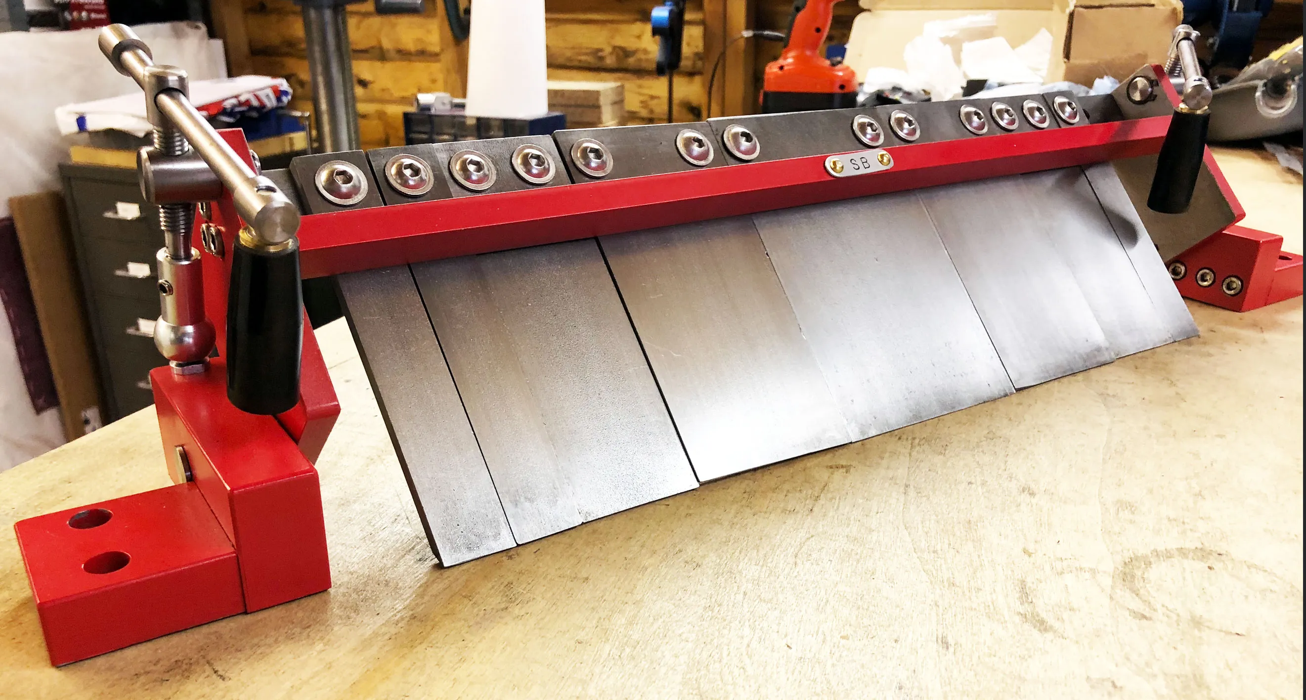
A thick pin on each side is the pivot point around which the top rotates as the screws are turned to raise and lower the fingers. This pin, the screw, the pin through which the screw turns and the handle (apart from the black plastic part) were all turned on a lathe out of bar stock.
The main construction of the brake is from cold rolled steel so that the sides are as flat and square as possible from the start, without any machining of surfaces. These are then just bolted together. Possibly the weakest part of the design is the 3 bolts on each side that attach the uprights to the base. These are under shear force when the brake is in use and I would come up with a different design for this if I was doing this again.
The main bar along the top has M8 threaded holes spaced 25mm apart. I was originally planning to use t-nuts and a slot to allow for infinite possible combinations of fingers in any position, but that was only adding complexity to the design. But this spacing combined with the slots in the fingers seems to offer many possible combinations of working length and you never need to reach behind to thread on a nut so is actually quicker to use. The bar is thick enough that the thread stripping should not be a problem, and also hopefully the bar will not twist while under load. To help, a thinner bar sits above the fingers so that the bending force does not want to just pull the bolts out.
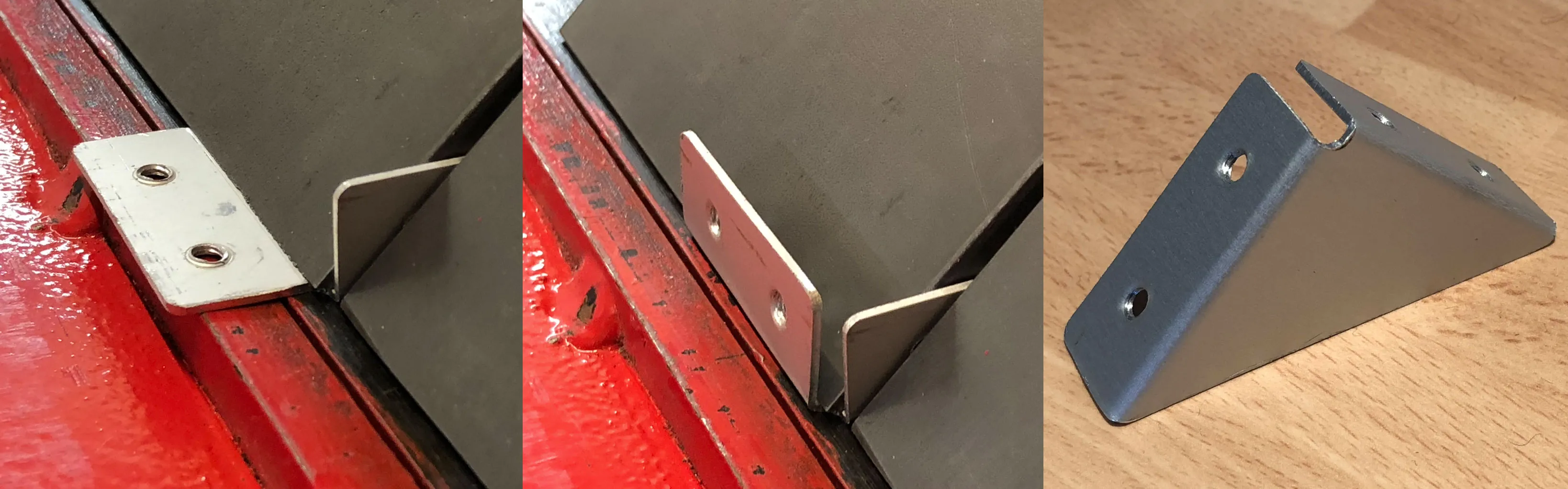
The fingers themselves are just 6mm steel with a hand-cut 45˚ chamfer on the bottom, ideally I would have done these on a mill to make them more consistent and a lot less manual labour. Hopefully the 6mm thickness will hold up. 8mm x 20mm slots for the bolts allow them to be spaced out as required.
The only modification required to the original brake was the drilling of additional holes on each side, so that a total of 4 M10 bolts could be used to clamp the whole thing down, instead of the 2 used originally.
So far I’ve only made some small parts with this, but so far it has held up to the light jobs I’ve used it for. Hopefully I never find out what its actual limit is.
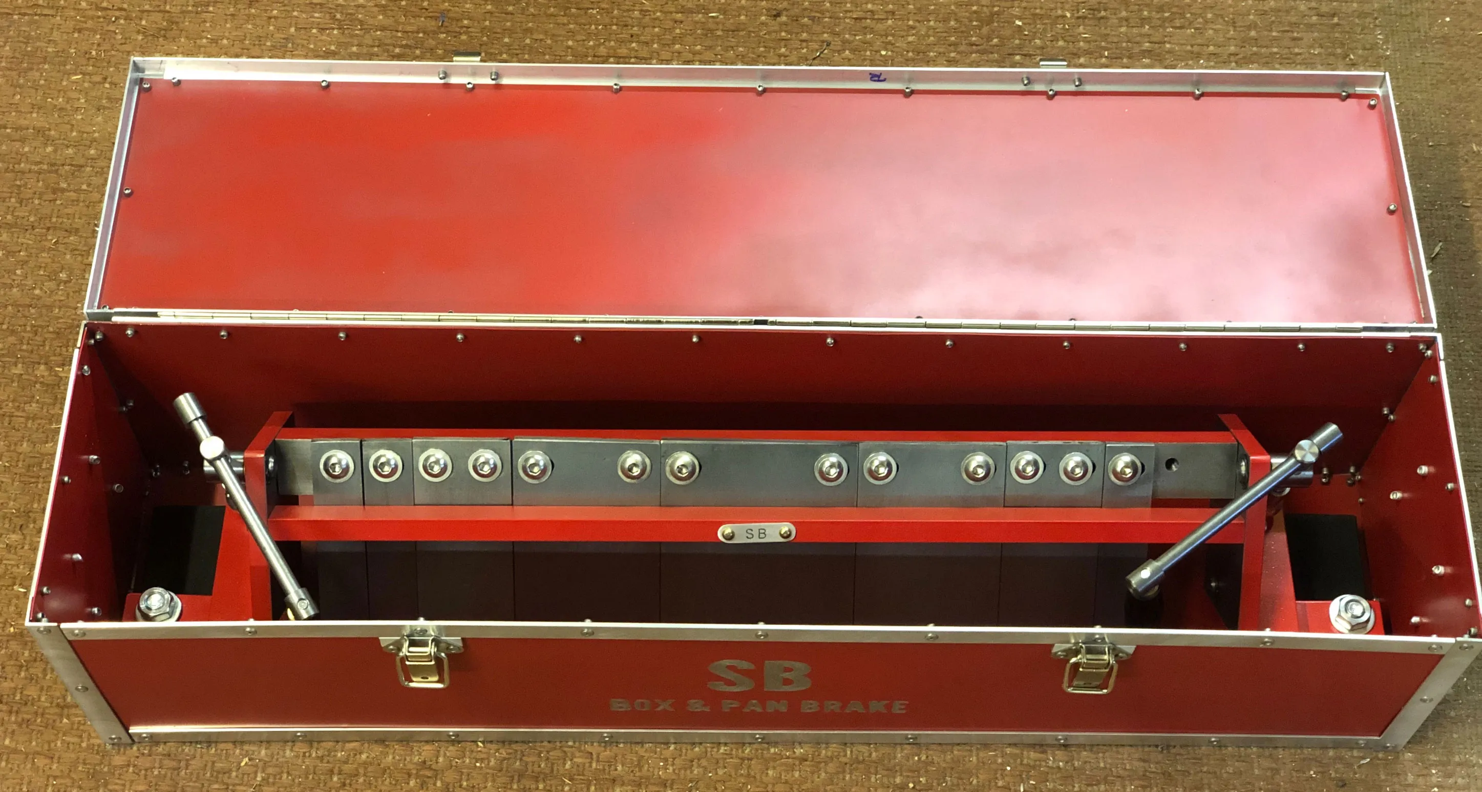
It’s an awkward size and shape for storing and also quite weighty, so with some spare metal I quickly riveted together a case for it in matching red with a bit of rough sign writing on the front. If only I had an even larger brake I could have folded the metal for the case instead of using flat sheets held together with angle…